Build examples
Below is a list of possible hardware implementations of ESP32-EVSE.
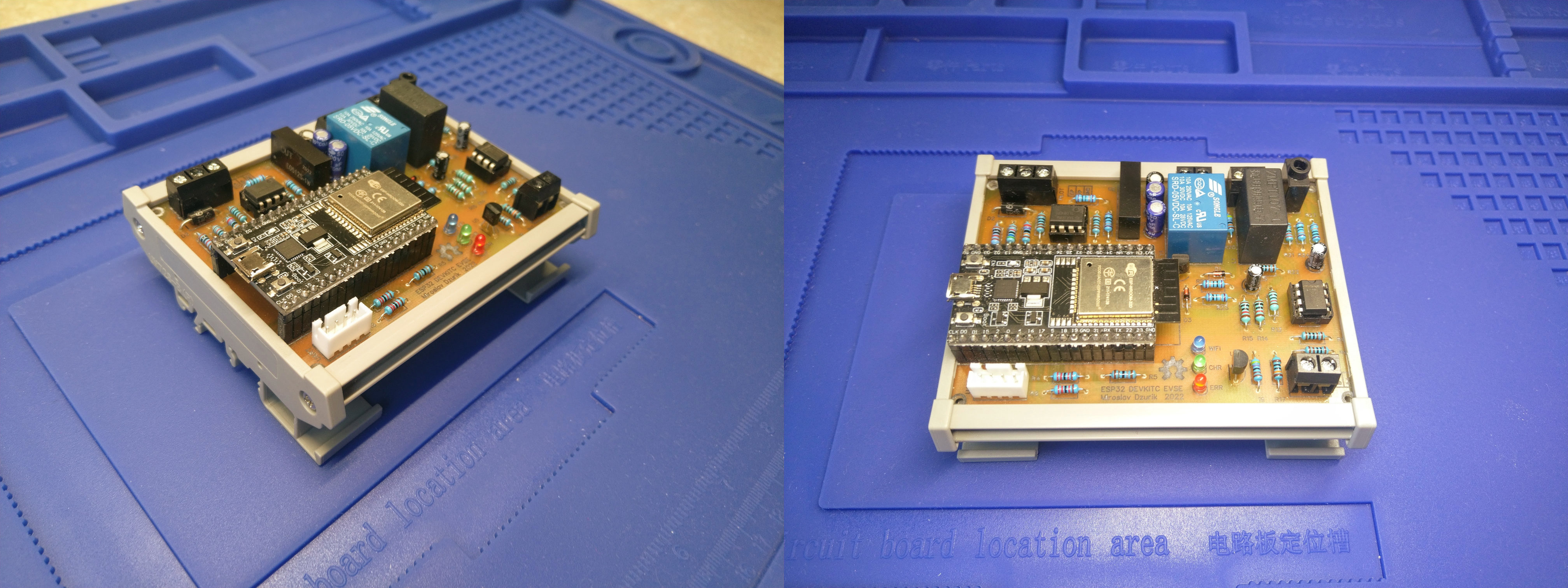
ESP32DevkitC EVSE~
Relying on a DEV board with basic functionality, such as single phase energy meter, RS485. One side PCB, discrete components, easier to assemble for DIY makers ;-)
You can order the PCB from the EasyEDA project page.
Standard electrical box~
ESP32-S2 EVSE DIY Alpha is meant to be reproduced by hand, the board favours discrete, through-hole components over dense surface-mount packages. The EasyEDA / OSHWLab listing publishes the complete schematic and PCB under GPL-3.0, and although it can be ordered pre-assembled, the through-hole approach is a deliberate choice that lets an individual builder populate, inspect and repair the board without specialised equipment. For a safety-relevant device that switches mains and monitors residual current, that openness and serviceability matter as much as the feature set.
- Hand assembly with basic tools. Through-hole resistors, capacitors, leaded semiconductors, the relay and screw terminals can all be soldered with an ordinary temperature-controlled iron. There is no need for solder paste, a stencil, a reflow oven or a hot-air station, and no fine-pitch or leadless (QFN/BGA) parts that demand a microscope and rework skills.
- Easy sourcing and substitution. Common through-hole parts are stocked by every distributor and tolerate substitution, so a build is not tied to a single reel or one supplier’s exact part number. That keeps the design reproducible and repairable years later.
- Mechanical robustness. Leaded parts and screw terminals are anchored in plated through-holes, so connectors, the relay and the terminals withstand vibration, thermal cycling and the mechanical stress of field wiring far better than components held only by surface pads.
- Room for mains creepage and clearance. The larger footprints and wider pad spacing of through-hole parts make it easier to keep the safety distances an AC mains device requires and to physically separate the high-voltage section from the logic.
- Inspectable and probeable. Every joint and component value is visible and reachable. You can clip a scope probe or meter onto a lead, lift a pin or tack on a wire without special tooling – valuable both for an experimental “Alpha” design and for verifying a board that handles mains.
- Easier heat handling. Leaded power parts and regulators shed heat and accept heatsinks more readily than small surface-mount packages.
The trade-offs are the familiar ones: the board is physically larger, takes longer to populate by hand, and is not what you would pick for high-volume production. For a one-off, openly published charging controller that a competent builder assembles, inspects and maintains, those costs are well spent.
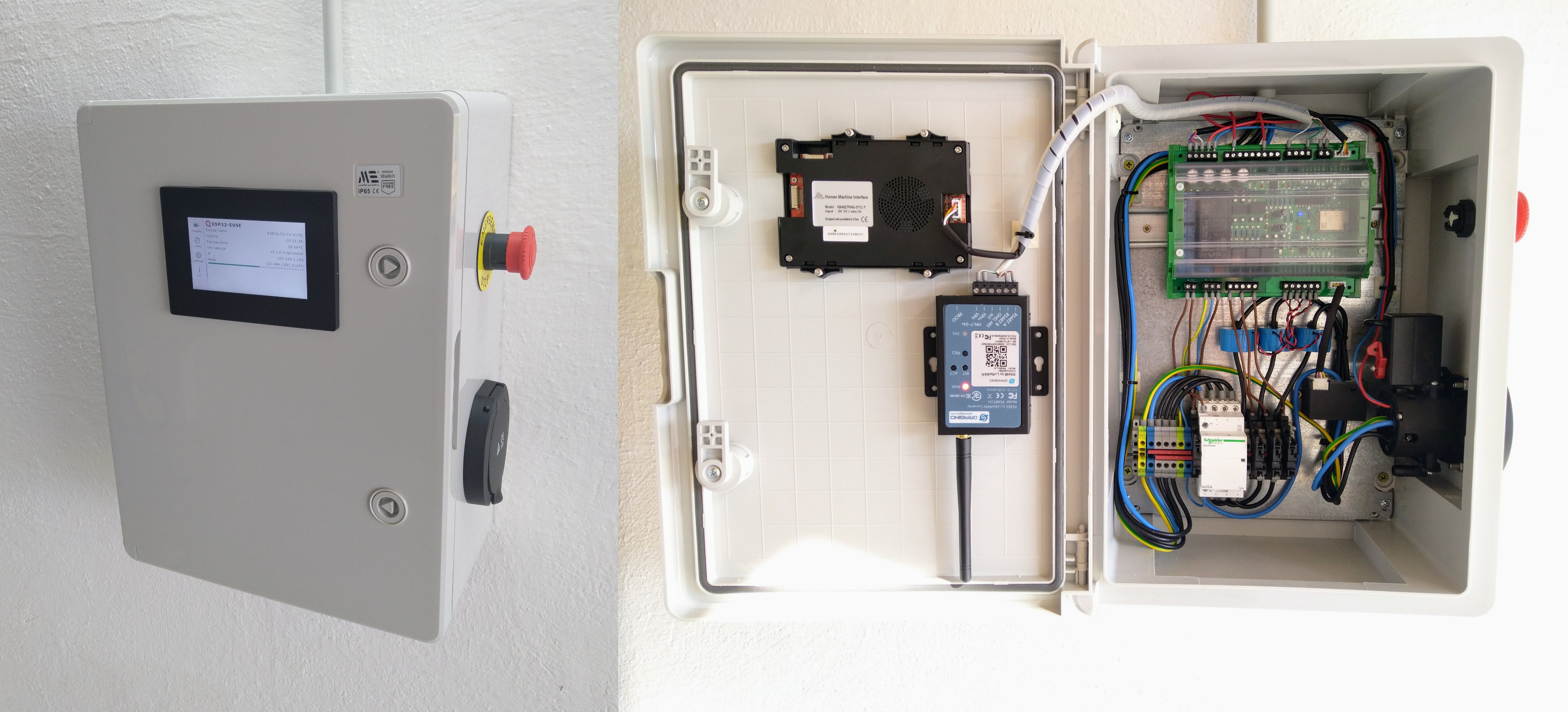
Placed in standard plastic electrical box (300x400x200mm); based on connection with socket outlet with additional features:
- Low tariff enable input
- RCM
- Nextion display NX4827P043-011C-Y
- Dragino LoraWAN module
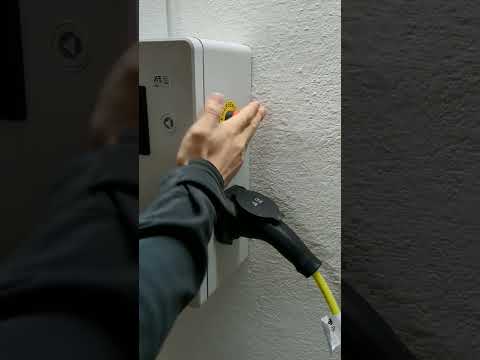
Quick demonstration video:
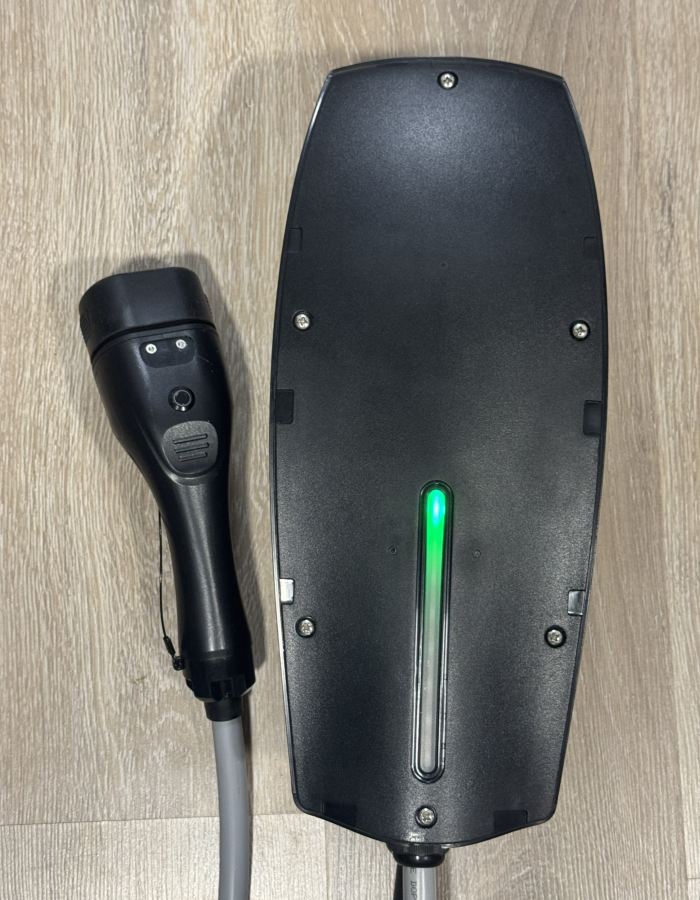
Tesla Wall Connector Gen2 box revived~
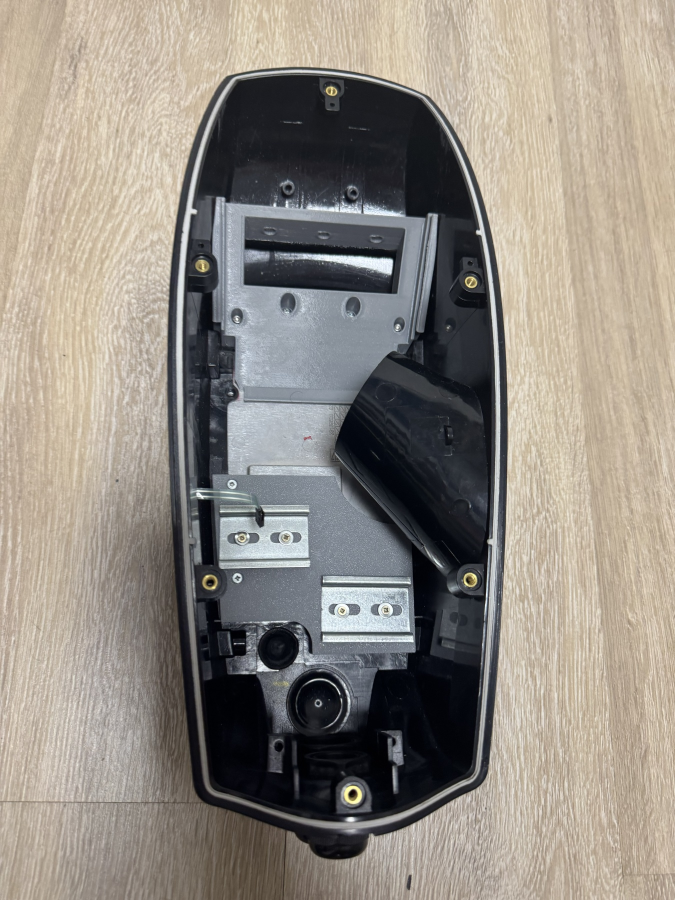
If you find a broken Tesla Wall Connector GEN2, it's worth reviving it because it has an exceptionally well built casing. Fire resistant and IP67 protected and also looking very good.
This box can accommodate ESP32‐S2 EVSE DIY Alpha very well. It fits into the upper area of the box, while the contactor and the optional surge protector can go in the lower area. The mid space is just enough to host the RCM and the current transformers.
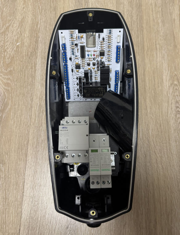
To hold the board and the DIN rail components you need to 3D print some parts. The board holder is tightened to the bottom of the box, in the original screw holes, but with longer M3 and M4 screws. The DIN rail holder screws on similarly with M3 screws.
If your Tesla Wall Connector Gen2 has the LED board also broken it can be replaced it with a piece of WS2812 LED strip. Used a separate ESP32C3 SuperMini board to drive it, and re-create light animations similar to how the Wall Connector behaves originally.
Plus benefit is, that with a simple RF transmitter module, 433MHz signals can be used to trigger opening of the charge flap on Tesla vehicles. Using the ESPHome component to interface with ESP32-EVSE not only integration with Home Assistant can be seamlessly achieved, but also implementing a physical button to both open the flap and stop charging (+releasing the cable from the car) thus the factory functionality of the Tesla Wall Connector can be simulated. The holder, spacer and the cover for the stip and the ESP32C3 SuperMini are also 3D printed.
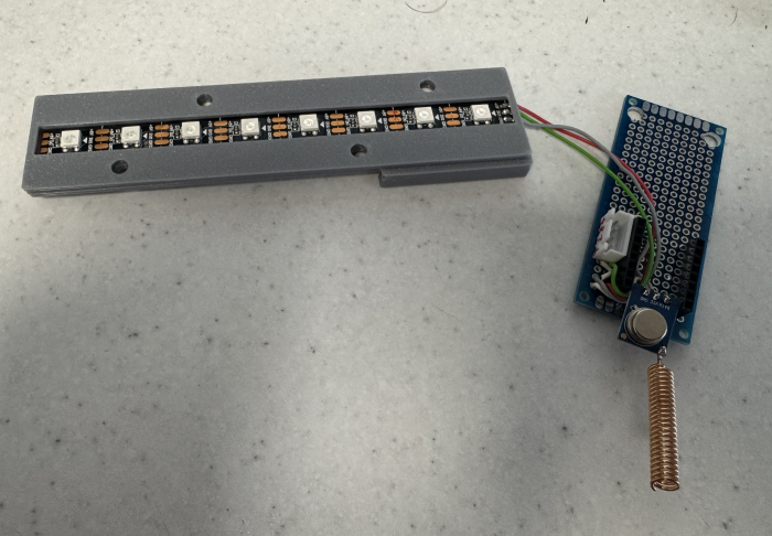
The ESP32C3 SuperMini also handles the reset button on the box, being multifunctional (different functions for short and long-press). ESPHome config here
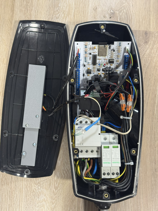
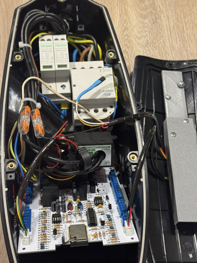
The contactor is 4NO 63A. A 7x6mm2 cable is suitable to transfer even 22kW if needed. It's cheaper than the EVSE dedicated cables, wires 6 and 7 can carry CP signal from the EVSE board and the button press signal to the SuperMini board. A small push button on the plug itself can be installed to replicate original functionality.
Use a RCM14-03 to detect AC and DC residual current leaks. Un-line fuse holders (with glass 5x20mm 32mA fast fuses) are appropriate for the voltage transformers behind the L1-L2-L2 connectors.
Note
The T3 surge protector is entirely optional and it's only effective if the facility you install this in has T1 and T2 surge protectors installed at the grid entry point and the distribution panel respectively. Using a T3 (or T1/T2) protector on its own will not protect from a lightning surge coming in though the grid. They are only effective as a system where they are deployed at a properly cabled distance from each other.
CAUTION
Working with high voltage is dangerous. Always follow local laws and regulations regarding high voltage work. If you are unsure about the rules in your country, consult a licensed electrician for more information.